Learn how to draw UML diagrams to document your Android applications. By Massimo Carli.
With a free Kodeco account you can download source code, track your progress, bookmark, personalise your learner profile and more!
Already a member of Kodeco? Sign in
With a free Kodeco account you can download source code, track your progress, bookmark, personalise your learner profile and more!
Already a member of Kodeco? Sign in
With a free Kodeco account you can download source code, track your progress, bookmark, personalise your learner profile and more!
Already a member of Kodeco? Sign in
Working on a real-world Android app isn’t just a matter of writing code. Most of the time you work in a team, and the code must be tested, but also well documented. Many people say that the code should be self-explanatory and you should understand how the app works just by looking at it. This isn’t completely true. Sometimes you need a way to represent the architecture of your app, check dependencies between different components or see how classes are related to each other. At the same time, you need to communicate with your colleagues in an easy but very expressive way using a quick diagram on a scratch paper or on a whiteboard. But how can you do that?
In this tutorial, you’ll learn everything you need to know to document your Android app using Unified Modeling Language (UML).
UML is a very big topic, but in this tutorial, you’ll see just what you need for a typical Android app.
Note: This tutorial assumes you’re familiar with Android development and Android Studio. If these topics are new to you, read the Beginning Android Development and Kotlin for Android tutorials first.
In this atypical tutorial, you won’t write a single line of code, but you’ll use the existing Poster Finder app.
Download the project by using the Download Materials button at the top or bottom of this tutorial. The app uses data from the Open Movie Database API website, which requires a free key and allows a maximum of 10,000 requests per day. Once you get the key, you need to add it to your local.properties file like this:
// . omdb_api_key="INSERT_YOUR_KEY_HERE"
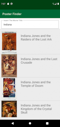
Build and run the app, insert the text Indiana into the EditText at the top and press Enter. You’ll get something like the following:
Poster Finder app
Poster Finder app
As you’ve probably guessed, you can use this app to search for a movie and display its poster by clicking on the image. You can play with the app and see how it works from a user’s perspective. But how does it work internally? How is the code structured? That’s what you’ll map out using UML.
You probably already know that UML is a standardized modeling language consisting of a set of diagrams. It was developed to help system and software developers specify, visualize, construct and document the components of software systems.
That’s an intimidating definition, and it might make you think that to use UML you’ll need some very complicated programs with expensive licenses. That’s not true — or, at least, it’s not true anymore.
Each UML diagram must be:
Although you can draw a UML diagram on a small piece of paper, in this tutorial you’ll use LucidChart.com. This is an online tool for creating some basic UML diagrams with a free account. This is just one of the tools you can find online. However, you could use any other tool or, of course, a piece of paper.
As stated earlier, each UML diagram should have a specific goal or answer a single question. You shouldn’t create a diagram to explain something that’s obvious.
In this tutorial, you’ll use UML diagrams to answer the following questions:
UML provides the tools to answer all those questions.
The Poster Finder app allows you to search for a movie by name and then displays its poster, if available. How can you represent the main use cases of the app with a diagram? In UML you do this using a use case diagram. That’s a way to answer the following questions:
Consider the following use case diagram.
Use Case Diagram

Use Case Diagram
What does it tell you? It tells you that:
This is the use case diagram for the Poster Finder app, but it’s also worth giving a quick example of a more complicated case.
With a free Kodeco account you can download source code, track your progress, bookmark, personalise your learner profile and more!
Already a member of Kodeco? Sign in